Bluetooth Low-Power Learning

So…I have a project I’m developing that requires Bluetooth. Basically, it’s an app to control some hardware I built.

I had an old HC-06 Bluetooth module lying around and it worked great. Was easy to get setup and connected to my Teensy microcontroller…but it only worked with Android. My iOS devices could not even see it. I later found out is was working on Bluetooth 2.0 and NOT the required 4.0 (BLE – Bluetooth Low Energy) required by iOS.

First of all, why do you need a BLE with iOS? Because they want a cut of the Bluetooth market and have specific requirements that are NOT part of the standard Bluetooth spec (what? Apple is doing their own thing? Say it ain’t so!!!!) However, BLE seems to get around this requirement. Ok, no big deal.

I found a device advertised as an HM-10 BLE module for Arduino that would connect to Android and iOS. Great! And it was inexpensive. Even better! It arrived after a few days and I was excited to hook it up and start testing my app on iOS.

However…

My iPad Mini could not see it. What?

My Android could see it, but could not connect to it. Double what??

I decided to hook up the module to the Arduino and wrote a quick little sketch to let me put it in AT mode (programming mode) and see if I needed to change any settings. That worked fine. Could communicate with it, but for some reason some of the AT commands would not work. So I typed in

AT+HELP
********************************************************************
* Command             Description			           *
* ---------------------------------------------------------------- *
* AT                  Check if the command terminal work normally  *
* AT+RESET            Software reboot				   *
* AT+VERSION          Get firmware, bluetooth, HCI and LMP version *
* AT+HELP             List all the commands		           *
* AT+NAME             Get/Set local device name                    *
* AT+PIN              Get/Set pin code for pairing                 *
* AT+PASS             Get/Set pin code for pairing                 *
* AT+BAUD             Get/Set baud rate		                   *
* AT+LADDR            Get local bluetooth address		   *
* AT+ADDR             Get local bluetooth address		   *
* AT+DEFAULT          Restore factory default			   *
* AT+RENEW            Restore factory default			   *
* AT+STATE            Get current state				   *
* AT+PWRM             Get/Set power on mode(low power) 		   *
* AT+POWE             Get/Set RF transmit power 		   *
* AT+SLEEP            Sleep mode 		                   *
* AT+ROLE             Get/Set current role.	                   *
* AT+PARI             Get/Set UART parity bit.                     *
* AT+STOP             Get/Set UART stop bit.                       *
* AT+START            System start working.			   *
* AT+IMME             System wait for command when power on.	   *
* AT+IBEA             Switch iBeacon mode.	                   *
* AT+IBE0             Set iBeacon UUID 0.            	           *
* AT+IBE1             Set iBeacon UUID 1.            	           *
* AT+IBE2             Set iBeacon UUID 2.            	           *
* AT+IBE3             Set iBeacon UUID 3.            	           *
* AT+MARJ             Set iBeacon MARJ .            	           *
* AT+MINO             Set iBeacon MINO .            	           *
* AT+MEA              Set iBeacon MEA .            	           *
* AT+NOTI             Notify connection event .                    *
* AT+UUID             Get/Set system SERVER_UUID .            	   *
* AT+CHAR             Get/Set system CHAR_UUID .            	   *
* -----------------------------------------------------------------*
* Note: (M) = The command support slave mode only. 		   *
* For more information, please visit http://www.bolutek.com        *
* Copyright@2013 www.bolutek.com. All rights reserved.		   *
********************************************************************

A help screen came back…and a lot of AT commands were not listed. At the bottom was “bolutek.com.” Crap.

After some more research, I found out I have a CC41A, NOT an HM-10. Then I read all about the “Clone Wars” regarding the HM-10 and all the manufacturers ripping it off. That research also yielded ways to tell if you have the original HM-10 (based on the TI CC2540 or CC2541 chipset.) The CC41A is also missing a crystal oscillator (the HM-10 has 2.)

In the meantime, I found an original HM-10 (at 3X the price of the clone, of course…but…worth it!)

However, when I hooked it up…SAME THING! Android could see but not connect, iOS could not even see it! WTH?!

After some digging around, I learned that BLE works differently from Bluetooth 2.0. First of all, no contracts. That means I don’t have to pair it to a device ahead of time. It’s all done “on-the-fly” so to speak.

I fired up my app and had it scan for BLE devices. Voila! It was there! On both iOS and Android. Lesson learned.

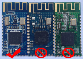
Here are two major ways to tell the clones from the righteous HM-10:

1. Second oscillator missing. This is a dead give away.  The image below shows two metallic rectangles above the black chip.  Those are the oscillators.  You’ll notice in the other two boards, the second one is missing.

2. Large chip on the board should say CC2541 or CC2540 (I know, this can be faked as well, but so far have not had that experience.)  Even if the chip DOES say CC2541 or CC2540, if the other oscillator is missing…it’s a clone.

HM-10-comparison

So, if you ever find yourself in need of something like this…beware. ALL of them are advertised as HM-10 with the CC2541/CC2540 chipsets. So far both have worked fine for me. If I ever have a more complicated project, I may stick with the HM10 as it has more capabilities.

Reporting for Duty

Well…notkt really….almost, though…

I have been working on my Stormtrooper armor (also known as a TK) for quite a while now and FINALLY got it finished in time for Halloween.

Why build Stormtrooper armor?  Is that even a question?  Do you event KNOW me?!!?!

Ultimately, I will be joining the 501st, a charitable organization….”Bad guys doing good.”  Check them out.

Meanwhile, Halloween was a blast (pun intended)!  Walking around the neighborhood, I can see why everyone tells me how fulfilling it will be to be in the 501st and bringing joy and smile to kids and adults alike.  Lots of photos were taken….lots of smiles on kids’ faces.  It was a blast.  Plus I was with Princess Leia and Rey..so…SCORE.

halloweenIt also was a great way to road test the TK Talkie system I designed.  It’s a cool vocal effects board that makes your voice sound like it’s coming over a radio and adds the obligatory sound effects when you stop talking (clicks and static bursts and such.)  It’s an open source project and highly customizable.  It worked wonderfully and really adds to the character of the costume.


A Little Election Fun with Lasers and Candidates

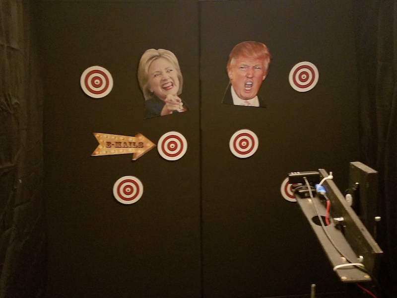
20161024_003006
I won’t waste a lot of time going in to how much everyone, no matter which party you support, has just about had it with the elections.  It’s gotten to the point that it’s unbearable.

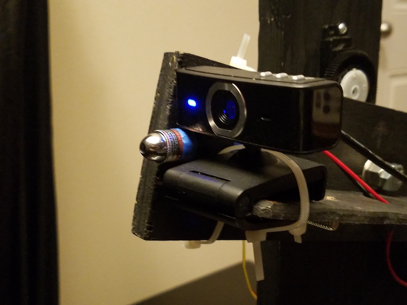
I decided to have a little fun by offering up something to let people take out their frustrations in a fun way.  I dusted off the old Internet-controlled paintball gun system and swapped it with a laser and put up a website where you could control it and have fun shooting targets!

Last year I worked with a German artist on a project called 11Days that allowed people to control a paintball gun in a rat enclosure.  Needless to say it caused quite a stir (don’t worry, the rat was perfectly safe) and made its point.  I used the same technology stack (again, with lots of modifications) and built an enclosure in my house.

The basic premise was this:

  • Allow people to control the “gun” via their browser
  • The laser would shoot targets and elicit soundbites from the candidate
  • Their eyes would flash each time a target of theirs was hit.
  • It kept high scores and had a leaderboard
  • It had the ability to record someone’s session and play it back in real-time (auto-pilot for the gun)
  • Videos of the user session could also be recorded and downloaded by the user

20161024_003052

The basic setup is this:

  • Local NodeJS server that controls the gun.  It attaches to a remote NodeJS server that handles the user interaction, queuing system, etc.
  • Local instance of FFMpeg that provides the camera stream.  It connects to a remote NodeJS server that handles the distribution of the stream to multiple clients.

All-in-all, three (3) NodeJS servers were used.  The website itself was built using Silex, which is a stripped-down version of the Symfony PHP framework.  There was an Arduino Uno controlling the servos (pan and tilt) for the gun and camera setup, and an Arduino Mega used to control the photoresistors embedded into each target as well as the LEDs used for the candidates eyes.  The soundbites were pulled from the interwebs and the music that played was a circus theme that I played with to make it sound all bent out of shape.

The video below was made and put on Facebook (via Youtube) and shows the setup in action.

TK Talkie – Custom Stormtrooper Voice Effects

NOTICE: This tutorial is out-of-date! The updated tutorial can be found at http://www.tktalkie.com/tutorial

.

This tutorial is for Version 1 of this project.  There is now a Version 2 available.  In order to build Version 2, follow the tutorial below, and the alternate steps for Version 2 are marked below.

It’s been a lifelong dream of mine (as well as many, many others out there) to own my own set of Stormtrooper armor. I, like may others, was finally able to do this when Anovos offered up their kits last year and made them super affordable.  Cue dream montage in 3…2…
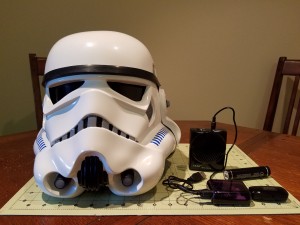
20160806_193439I’ve had a blast building my kit and helping and being helped in the process by so many great people that are so ready to offer up their knowledge via the Anovos Facebook group and of course WhiteArmor.net.

So here’s my attempt at giving back.  I purchased a wireless mic system from Wireless Trooping Systems and an Aker 10 watt speaker off eBay, but wanted to add the really cool voice effects.  You can buy effects boxes, and they are all great, but I, like so many, am on a budget (putting 2 kids through college with a 3rd on the way is NOT cheap lol…)

I love to tinker with Arduinos and such, and stumbled across a video for the Teensy 3.2 and the Teensy Audio Shield and was blown away by what it could do.  And it’s inexpensive.  I started thinking…”what if…”

Fast-forward about a week later and I have a pretty decent working voice-effects box for around 50.00 (not including the speaker or the wireless microphone system…which is awesome btw..)  It was not very difficult.  I built on the plethora of examples and tutorials that come the Teensy software.  And to date, it has the following features:

  • Is voice-activated (no Push-To-Talk…but it could be added pretty easily)
  • Is fully customizable – From the startup sound to the effects, you can use pretty much whatever you want (though honestly, there are only a few TK voice effects to realistically use)
  • Did I mention it is FULLY customizable? Since you have the source code you can do pretty much whatever you want with it!

You can get the source  code and instructions from my Github repository.

Ok, enough chatter (see what I did there?) Let’s get to it!

Stuff You’ll Need

I built my effects box using a Teensy 3.2 and Teensy Audio Shield, although you can actually use other boards if you want.  Teensy is pretty powerful and just makes it easy!

If you are building Version 2, you’ll need to get the pre-pinned Teensy, or else solder your pin headers the same as the pre-pinned Teensy. YOU WILL NOT NEED THE SOCKET SET OR THE HEADER PIN SET LISTED BELOW.

The following are optional, but I recommend grabbing them:

Tools You’ll Need

  • Soldering iron and solder
  • Magnifying headset if you’re over 40 like me and can’t see anything within a foot of your face 😉
  • Wire
  • Wire strippers

The following are for making an optional case:

  • X-acto knife (for fine trimming)
  • Drill and various size drill bits
  • Some type of work mat (if you are working on your kitchen table like me)
  • Needle (or small) files

Getting Started

NOTICE:  The link to the Arduino software below is the general downloads page…the current version of the TeensyDuino software DOES NOT work with the latest version of Arduino (1.6.9 as of this writing) so you’ll need to grab an older version.

Once you have your Teensy and Audio Shield in hand, you’ll need to install the Arduino software as well as the Teensy software, called TeensyDuino.  Take some time and familiarize yourself with the examples and tutorials under File > Examples > Audio and File > Examples > Audio > Tutorial.  There is a lot of great stuff there.  Additionally, watch the Teensy Audio Tutorial and Workshop video on Youtube to get an idea of what you can do with this awesome piece of tech!

If you are impatient, then just keep reading 🙂

Install the Software

Once you have downloaded the Arduino and TeensyDuino software, install the Arduino software FIRST.  Then, install the TeensyDuino software (you’ll need to tell it where the Arduino software is located.)

Soldering and Connecting the Boards

If you are building Version 2 using the pre-pinned Teensy (or soldering the pins on the same way as the pre-pinned version), skip the steps regarding the header pins and sockets and just solder the Teensy directly to the Audio Shield according to the directions in the Version 2 tutorial, being careful to align the pins correctly. (See Version 2 for reference.)
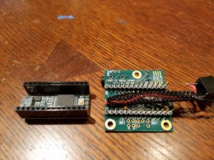
I actually soldered mine backwards, with the sockets on the Teensy and the header pins on the Audio Shield

I actually soldered mine backwards, with the sockets on the Teensy and the header pins on the Audio Shield

If you did not get the pre-pinned Teensy, then you’ll need to solder the header pins on the Teensy.  Then solder the sockets on the Audio Shield.  Put the short end of the header pins on the “top” of the Teensy…that is, the side that has the micro USB connector and the programming button.  The long part of the pins should point up and away from the side with the usb connector and button.  On the Audio Shield, solder the short end of the socket pins to the underside…or the side that has the SD card reader and headphones jack.  The long end of the sockets should be on the opposite side.  It’s important to get these right so that the connections are correct when you put these together!

Once you have everything soldered up, connect the shield to the Teensy, being careful that the pins are lined up correctly.  Check the 4 corner pins on each board and make sure they will line up with you connect the boards together.  They are (clockwise, holding the Audio Shield looking at the side opposite the SD Card reader and headphone jack)

  • GND (ground)
  • 12
  • 13
  • 5V

If everything is lined up, the micro USB of the Teensy and the headphone jack of the Audio Shield should be facing the same direction.

Sound Files

You can make your own WAV files, or you can download a zip file with WAV files to get started.   Be sure to read the READ.me file listed in the repo regarding WAV files, but here’s the short of it:

  • WAV files can be 16-bit mono or stereo at 44,100Khz.  You can try other bit rates, but those are the ones that seem work best
  • The SD card reader expects the files to be in old-school 8.3 format and all UPPERCASE.  That is, the file name can have up to 8 characters and the extension has 3.
  • The way the software is CURRENTLY written (remember, you can change it however you want) it looks for a file named STARTUP.WAV when it first boots up and plays that, then reads all files that start with “TKT_” and loads them into a list that it will randomly select from each time an effect is played.
  • Try to keep all your WAV files at the same volume level.  If they are not, you’ll have weirdness where some effects are louder than others. There are lots of free WAV file editors out there that will let you add or remove gain from your WAV files.

If you have downloaded the zip file, go ahead and unzip and load these files onto your micro SD card and then insert into into the SD card reader on the audio shield.

Status Check
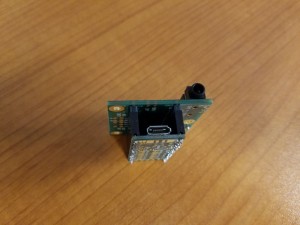
Teensy and Audio Shield with headers and sockets soldered and connected together

Teensy and Audio Shield with headers and sockets soldered and connected together

See how easy this is so far?  By now, you should have

  • Arduino and TeensyDuino installed
  • Sockets and header pins soldered onto Teensy and Audio Shield and boards connected
  • Sound files loaded on micro USB card and card installed in SD card reader of Audio Shield

Loading the Software

Connect the Teensy with the USB to micro USB cable.  Plug the micro USB end to the Teensy and the USB end to your computer.  You should see the on-board LED light up.  This means you have power 🙂  Next:

  • In the Arduino software, go to Tools > Board and make sure to select the correct board (in this case, Teensy 3.2/3.1).
  • Go to Tools > Port and select the correct serial port (the one your Teensy is connected to)
  • Download the tktalkie.ino file from the Github repo (remember where you download it!)
  • Go to File > Open in the Arduino software and open up the tktalkie.ino file

Once the file is opened, click the “Upload” button (the one that looks like an arrow pointing right.)  If everything is connected correctly, the sketch should compile and load onto your Teensy.  Then the board should restart and you should hear the STARTUP.WAV file play (oh yeah don’t forget to either connect your speaker to the headphone jack on the audio shield or plug in some headphones…)

If the sketch doesn’t load (i.e. you get an error in the Arduino window), make sure your pins are connected correctly and that you have selected the correct board and serial port (see above.) Also make sure the volume is turned up on your speaker 🙂

Then unplug everything because you have some more soldering to do…

About the Software

I used the BitCrusher component to compress the voice and lower the pitch just a tad so it sounds like a crappy old walkie talkie.  The software sketch is commented pretty heavily so that you know what’s going on.  Feel free to play around with it and tweak to your liking! Again, take a look at the READ.me file on the Github repo.

Connecting the Microphone

20160806_211633

Panel mount 1/8″ stereo input jack soldered to Audio Shield. Note the jumper between the left and right input channels on the jack since the microphone input on the Audio Shield is mono.

You can either use the microphone input on the audio shield or the line-in.  It’s easier to use the microphone (IMO), but feel free to use the line-in if you want (that just means you’ll need to use some type of powered input signal.)  The microphone is mono with a single positive lead and a ground, and I used a stereo input jack, so I just jumped a wire between the left and right pins on the jack and then soldered the microphone to the board.  Make sure you solder the ground on the input jack to the ground on the audio shield.

Once this is done, you have a “complete” system.  You should be able to connect everything back up, including connecting a microphone, fire up the board (you can use the 5V power supply at this point or just keep using your computer’s USB port,) hear the STARTUP.WAV file, then start talking and hearing voice effects!

Now It Needs a Box…

The last part of this project is putting it in a protective box so that you can troop with it without worrying about it getting damaged.  I went to the local Fry’s and looked for a project enclosure and actually bought a few to try out, but they were all to big or not tall enough or too tall (and as you know, you have limited room in the TK outfit…)

As luck would have it, I had recently upgraded my phone to a Galaxy S7 and as it turns out the plastic box that the headphones come it is almost perfect for the job!  The boards can squeeze in there and be held pretty safely in place!  Yay!

So in the last part of this tutorial I’ll show you how I mounted it in the headphones case 🙂

Make a Base

In order to prevent the board from rattling around inside the box once it was closed, I took the sticky foam pads from inside the TK helmet (if you’ve done any helmet upgrades you know what I’m talking about 😉 ) and cut out a rectangle shape and stuck it to the bottom of the case.

Trimmed down sticky pad from inside the TK helmet.

Trimmed down sticky pad from inside the TK helmet.

The only bad thing about the case is that it curved on the sides, so in order to get the board to sit flush I would have to make openings a little larger in order to get to the connections.  Not a big deal, I need this to work, not look pretty (although…to be honest…I would like it to look SOMEWHAT pretty) since it will be mounted behind my chest plate.

Next, I test fitted the boards and marked where I would have to make openings for the micro USB, headphone and microphone jack connections.  Since this case has a top and a bottom, I would have to make cuts in both.

Make Some Holes

After test fitting and marking where to cut, I got out the trusty Dremel with a cutting wheel and some needle files (if you don’t have needle files….bro? Do you even cosplay?)  Also an X-acto knife comes in handy for some finer trimming.

I cut the opening for the micro USB first since it was on the bottom and I needed to make sure it went low enough so that when the boards are resting on the bottom of the case I could plug in the micro USB cable.

Cutting the opening for the micro USB connection.

Cutting the opening for the micro USB connection.

Next, I marked where the headphone jack would need to be accessible through the top part of the case and started by drilling a 1/16″ pilot hole, then eventually ended up using a 1/4″ drill bit and widening the opening to make sure the speaker connector could be plugged in.  Each time I cut an opening, I used the needle files to smooth it out and the x-acto knife for fine trimming as the plastic was soft enough that it started to melt from the Dremel or drill if I went too fast.
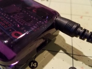
At first the opening was too small, so I had to go back with a larger bit to open it up more and then use the files to smooth it out so the entire connector would fit.

At first the opening was too small, so I had to go back with a larger bit to open it up more and then use the files to smooth it out so the entire connector would fit.

Also, once I had the openings for the micro USB and headphones cut out, I put the boards in the box and closed it up for another test fit and noticed that I didn’t actually have the clearance I though I had so the board kind of sat lop-sided.  Oops!  Oh well, like I said, this needs to work more than it needs to look pretty, plus it ended up holding the board pretty securely in place!

20160806_183920

Oops! Turns out the box was not as tall as I thought! I could still access the connections, though…so all good.

Microphone Jack

I chose a panel mount microphone jack because I knew that whatever I ended up using for an enclosure, I would want it accessible from the outside (as is normal.)  However, with this one, I would need to make cuts in both the bottom and top of the case in order to get it to fit.

Had to make an opening in the bottom of the case and then cut a notch out of the lid for the microphone jack.

Had to make an opening in the bottom of the case and then cut a notch out of the lid for the microphone jack.

Putting It All Together

Once I was done with the openings for the connections, I was able to close up the case, hook everything up and voila!  It works great!
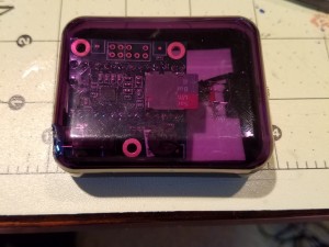
Case closed.

Case closed.

I hope this tutorial was helpful, and I hope if you make this project you have as much fun as I did.  Like I said, there are LOTS of things you can do to this project (like add a PTT button if you want.)

For the Empire!
 

11 Days – Shooting a Rat on the Interwebs!

From the art project "11 Days" by artist Florian Mehnert

From the art project “11 Days” by artist Florian Mehnert

The Beginning…

Last year I was contacted by an artist from Germany regarding the web-controlled paintball gun that I had built.  He said he wanted to use it in an art project he was planning and wanted to know if I would be willing to help him build his own paintball turret that could be controlled via the internet.

Since my original intent for building the paintball gun was to allow people to control it over the internet (but, alas…life and all that got in the way) I was excited to have the opportunity not only to provide assistance, but to finally see that vision realized.  I mean, how cool is it to be able to control something like that over the internet…but how much cooler to control it when it’s half-way around the world!

After several months of e-mails back and forth, we started in earnest around December of 2014.  I sketched out the basics of the design and gave him a hardware list.  He had constructed his own base for the turret which I thought was a very elegant and simple design.  I sent him wiring schematics and in short order he had a working paintball turret.

The Setup…

The next thing was for me to update the software that would be needed to control the gun.  I had written several versions of the software previously, including one that allows people to vote via hashtag on Twitter and have the paintball gun shoot some pre-programmed target based on the the tally, but I needed to make sure it would be robust enough to handle a LOT of traffic PLUS I had to add a queuing system and some other features.

I won’t go into all he boring details here (I’m more than happy to do that if you want to contact me to discuss the project, however…) so here is a summary of what was used and how it was setup.

The first thing to figure out was how all of the moving parts would fit together.  After a couple trials, I decided on a distributed approach that consisted of:

  • Local installation of FFMPEG on a computer with a webcam connected – This was used for live video streaming.  FFMPEG notes itself as being the “Swiss Army Knife” of video tools…and it’s true!
  • Local installation of Node JS on the same computer – this system was basically a pass-through from the web layer (explained later)…in other words, it had a minimal configuration that told it about the servos (min/max angles, etc.) and was responsible for communicating with the Arduino to control the servos for the paintball gun.
  • Remote installation of Node as a streaming server – the local video stream connected to the remote streaming server for video distribution.
  • Remote installation of Node as web server and socket server that would interpret client movement in the browser and translate coordinates appropriately and send them to the local Node server to control the paintball gun.
The rat's "cage"

The rat’s “cage”

This type of setup gives maximum flexibility and allows for variations in implementation…in other words, the “middleware”, so to speak, at the web server layer is responsible for making sure that the translated user movements fit within the limitations of the local configuration.  If you want to change the experience…say, the way the user can move the paintball gun, for example…you could do that by changing just the middleware layer and leave all of the other stuff alone.

In a nutshell, it works like this:

  1. A configuration file (in JSON format) defining servos, min/max/home angles and communication settings is loaded by the local Node installation.
  2. The local Node instance then communicates to the Arduino and sends this configuration (the code on the Arduino is also basic in that it performs minimal checking of angle limits, etc.)
  3. The local Node instance then connects to the remote instance (defined in the config file) and sends these same settings.
  4. Users connect to the remote Node server, which acts as both web server and socket server.  The size of the video display area is sent to the web server which then calculates a movement ratio based on the settings received from the local Node instance.  This way, the user’s movements on screen are more accurately translated into the paintball turret’s movements.

The video server was a very simple setup:  FFMPEG running on the local computer connecting to a remote streaming server (also Node JS.)  When a user connects to the website, a video streaming socket is also opened so that they can watch as other people move the turret around.

One of the major benefits of this setup was that the artist’s internet connection at his studio did not have to be hugely robust (decent, but not super fast) as all the heavy lifting would be handled by the remote server. After all, it was only used for the video stream and basically-one way communication to the local Node controller (in, fact, if not for the video stream, the connection would not need to be very fast at all.)

The Premise…

The artist, Florian Mehnert, had caused some controversy with his previous art projects (just Google Florian Mehnert) and this project was not going to disappoint.

As a sort of protest against the use of drone strikes, he was going to allow people from all over the world to control a gun (no one knew is was a paintball gun at the time) and be able to shoot a rat at the end of an 11 day countdown.

Long story short, the project caused all kinds of commotion over in Europe, leading to extreme spikes in traffic on the website and news reports, even death threats.  In fact, the threats got so bad that the experiment ended early and the rat was removed from the experiment (don’t worry, the rat was never actually going to be shot.)

If you visit the site now, you’ll see the true intent and message of the project.

I had planned on posting all of the code to GitHub, but have not had the time to get it prepared for public use.  However, if you think you would like to experiment with the code in your own, project, just drop me a line.